Brilliant Tips About What Frequency Should I Use For PWM

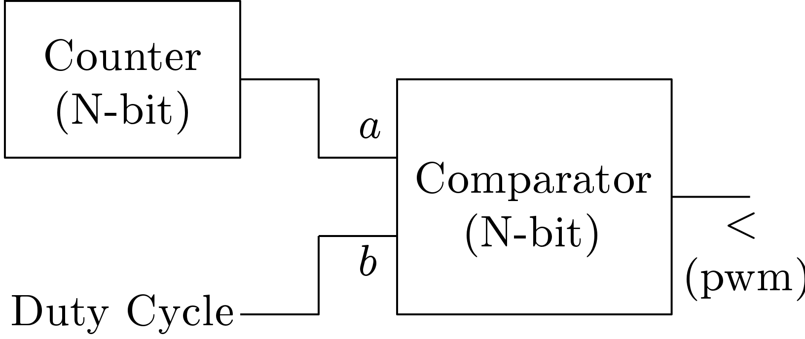
How To Generate High Frequency PWM Signal Using Arduino Uno R3
Decoding PWM Frequency
1. Understanding the Basics
Pulse Width Modulation, or PWM, is like the maestro of the electronics world, conducting signals with precision. Think of it as rapidly switching a signal on and off. The magic lies in the 'duty cycle' — the proportion of time the signal is 'on' versus 'off'. This dance of on and off allows us to control things like motor speed, LED brightness, and even the power delivered to a heating element. It's a clever way to mimic an analog signal using a digital one. But here's the kicker: the frequency at which this on-off switching occurs is crucial. Too low, and things might flicker or buzz annoyingly. Too high, and you might run into efficiency problems. Finding the right PWM frequency is the key to harmonious operation.
Essentially, we're trying to trick the system into thinking it's receiving a continuous signal. Imagine dimming a light bulb. Instead of constantly reducing the voltage, PWM rapidly turns the light on and off. If the on-time is longer, the light appears brighter. If it's shorter, dimmer. The faster this happens, the smoother the dimming effect. This clever method reduces heat and power waste. Thus, selecting the perfect PWM frequency is critical to maintaining precision and efficiency.
So, how do we navigate this electronic labyrinth? Well, that's precisely what we're going to untangle. There's no one-size-fits-all answer, sadly. It depends heavily on what you're controlling. Is it an LED? A motor? A speaker? Each application has its own sweet spot, a range where the PWM frequency works best. Ignoring these intricacies can lead to everything from flickering LEDs to overheated components. Think of it like choosing the right music for a party you wouldn't play heavy metal at a tea party, would you?
The good news is, we'll give you some guidelines to help you choose the right frequency for your needs. We'll also touch on the trade-offs and considerations to keep in mind. After all, a little knowledge can go a long way in making your electronic projects sing (or hum, or whir, depending on what they do!). Let's dive in and see how to get the most out of PWM.

Pwm Circuit Diagram Using 555
LEDs
2. Finding the Flicker-Free Zone
When it comes to LEDs, the primary concern is usually preventing flicker. Our eyes are surprisingly sensitive to changes in light intensity. If the PWM frequency is too low, you'll see that annoying strobing effect. The lower the frequency, the more pronounced the flicker. It's not just visually unpleasant; prolonged exposure to flickering light can even cause headaches or eye strain. Not the desired effect when trying to illuminate your project!
So, what's the magic number to banish the flicker? Generally, you want to aim for a PWM frequency of at least 100 Hz. This means the LED is turning on and off 100 times per second. Most people won't perceive any flicker at this frequency. However, for sensitive applications or when using particularly bright LEDs, you might want to go even higher, perhaps 400 Hz or even 1 kHz. It's all about striking the right balance between performance and potential side effects. Remember, higher frequencies can sometimes introduce more switching losses, potentially reducing efficiency, but this is usually negligible for LEDs.
Here's a little secret: experiment! Start with a frequency around 100 Hz and slowly increase it until you can't detect any flicker. You might be surprised at how sensitive your eyes are. Also, the type of LED can play a role. Some LEDs respond faster than others. Higher quality LEDs will typically handle higher PWM frequencies without issue, offering more flexibility in your design.
Keep in mind the application as well. If you're controlling a simple indicator LED, 100 Hz might be perfectly adequate. But if you're using PWM for sophisticated color mixing or creating dynamic lighting effects, you might need a higher frequency to achieve smooth transitions and avoid any visible stepping in the color changes. Now go forth and conquer the flicker!

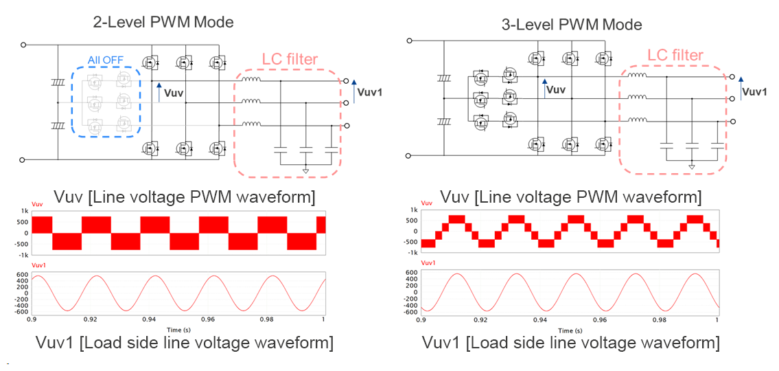
PWM Strategy (a) Sine And Triangular Waveform (b) S1/S4 Pulses (c
Motors
3. Silencing the Squeal
Motors introduce a whole new set of considerations. Low PWM frequencies can cause motors to vibrate, make noise, and generally behave erratically. Think of it like trying to drive a car with a jerky clutch — not exactly a smooth ride! The motor will struggle to maintain a consistent speed, especially at low speeds.
For small DC motors, a PWM frequency between 1 kHz and 20 kHz is often a good starting point. The exact frequency will depend on the motor's characteristics, its load, and the application. The goal is to find a frequency that's high enough to provide smooth control but low enough to avoid excessive switching losses in the motor driver circuitry. This is particularly important for battery-powered applications, where efficiency is paramount.
However, here's the tricky part: audible noise. Some PWM frequencies can fall within the audible range, causing the motor to emit a high-pitched whine or squeal. This is especially noticeable with cheaper motors or in quiet environments. If you're experiencing this, try increasing the PWM frequency above 20 kHz, outside the range of human hearing. Just be aware that higher frequencies may necessitate using more robust motor driver components capable of handling the increased switching speed.
Pro-tip: listen carefully! If you can hear a distinct whine coming from your motor, it's a sign that the PWM frequency needs adjusting. Experiment with different frequencies until you find the sweet spot where the motor runs smoothly and quietly. Also, consider adding a snubber circuit to the motor to help reduce electromagnetic interference (EMI) and further minimize noise. Happy motoring!

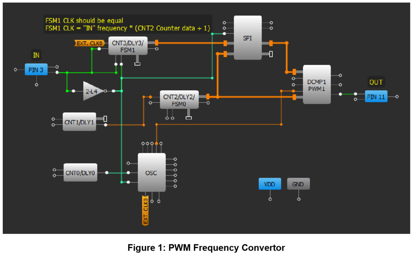
Implementing A Pwm Generator With Adjustable Frequency And Duty Cycle
Audio Signals
4. Preserving the Purity of Sound
PWM is occasionally used in audio applications, particularly in Class-D amplifiers. The principle is the same — rapidly switching a signal on and off to mimic an analog signal. However, when dealing with audio, fidelity is king. You want to reproduce the sound as accurately as possible, without introducing any distortion or unwanted noise.
The key consideration here is the Nyquist-Shannon sampling theorem, which states that the sampling frequency (in our case, the PWM frequency) must be at least twice the highest frequency you want to reproduce. Human hearing typically ranges from 20 Hz to 20 kHz, so ideally, you'd want a PWM frequency above 40 kHz. In practice, most Class-D amplifiers use much higher frequencies, often in the hundreds of kilohertz range, to ensure minimal distortion and excellent audio quality.
However, there's a trade-off. Higher PWM frequencies can lead to increased switching losses and require more sophisticated filtering to remove unwanted high-frequency noise from the output signal. This adds complexity and cost to the design. Therefore, choosing the right PWM frequency for audio applications involves carefully balancing fidelity, efficiency, and cost. Consider factors such as total harmonic distortion (THD) and signal-to-noise ratio (SNR) when making your decision.
In audio, experimentation is key. Listen carefully to the output signal at different PWM frequencies. Use an oscilloscope to examine the waveform and look for any signs of distortion or unwanted noise. It's also wise to consult the datasheets for your audio amplifier components, as they often provide recommendations for optimal PWM frequencies and filtering techniques. Listen up, and let your ears guide you!

General Guidelines and Considerations
5. Balancing Act
Choosing the correct PWM frequency is often a balancing act between several factors. Higher frequencies generally lead to smoother control and reduced noise, but they can also increase switching losses, reduce efficiency, and require more robust components. Lower frequencies, on the other hand, can be more efficient but may result in noticeable flicker, vibration, or noise. It's all about finding the sweet spot that works best for your specific application.
One important consideration is the switching speed of your components. MOSFETs and other switching devices take a certain amount of time to turn on and off. If the PWM frequency is too high, these switching times can become a significant portion of the duty cycle, reducing efficiency and potentially causing overheating. Always consult the datasheets for your components to determine their maximum switching frequency.
Another factor to consider is electromagnetic interference (EMI). Higher PWM frequencies can generate more EMI, which can interfere with other electronic devices. This is especially important in sensitive applications such as medical devices or wireless communication systems. To mitigate EMI, consider using shielded cables, filters, and proper grounding techniques. EMI is like that annoying party guest who shows up uninvited and messes everything up, so be sure to take precautions to keep it at bay.
Finally, don't be afraid to experiment! There's no substitute for real-world testing. Start with a reasonable PWM frequency based on the guidelines we've discussed, and then tweak it up or down until you achieve the desired performance. Use an oscilloscope to monitor the PWM signal and look for any signs of distortion or unwanted noise. Remember, every application is unique, and the optimal PWM frequency may vary depending on the specific components and operating conditions. So, roll up your sleeves, get your hands dirty, and have fun!
